the logic circuit shown in the diagram directly implements
The circle on the symbol is called a bubble and is used in logic diagrams to indicate a logic negation between the external logic state and the internal logic state 1 to 0 or vice versa. The circuit diagram of the proposed DC motor speed controller can be seen.
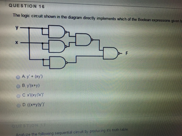
Solved The Logic Circuit Shown In The Diagram Directly Chegg Com
The reset circuit of the microcontroller consists of a 10K resistor 10uF capacitor and a push button.
. 6 to 30 characters long. This library provides some example code also that can be found in File - Examples - FreeRTOS as shown below. One of the first uses of the term protocol in a data-commutation context occurs in a memorandum entitled A Protocol for Use in the NPL Data Communications Network written by Roger Scantlebury and Keith Bartlett in April 1967.
Then only segment a will be illuminated. DNA nanotechnology is the design and manufacture of artificial nucleic acid structures for technological uses. We show how to run QFT on a simulator and a five qubit device.
There is a difference between a user interface and an operator interface or a humanmachine interface HMI. On the pins labeled A0-A5 we use an external circuit to scale down the input voltage from 33V. Fourier optics is the study of classical optics using Fourier transforms FTs in which the waveform being considered is regarded as made up of a combination or superposition of plane wavesIt has some parallels to the HuygensFresnel principle in which the wavefront is regarded as being made up of a combination of spherical wavefronts also called phasefronts whose.
Looking at the shown circuit diagram the idea can be explained with the following points. The current level through the motor decides it speed and thus implements the controlling effect via the pot. The frequency of the output from the IC may be calculated with the formula.
B Abstract diagram of logic circuits that react with input Layer 1. 4 Recommended Documentation 41 Manuals Schematics. On a circuit diagram it must be accompanied by a statement asserting that the positive logic convention or negative logic.
This circuit allows the XADC module to accurately measure any voltage between 0V and 33V relative to the Arty Z7s GND that is applied to any of these pins. The Circuit that Implements the QFT. R1 P1 C2 needs to be calculated at 50Hz using this 555 IC calculator.
If both of the A and B inputs are high then both the NMOS transistors bottom half of the diagram will conduct neither of the PMOS transistors top half will conduct and a conductive path will be established between the output and V ss ground bringing the output low. In this tutorial we introduce the quantum fourier transform QFT derive the circuit and implement it using Qiskit. The following diagram shows how filter types interact in the filter pipeline.
They run only when the action method has executed successfully. On the ARPANET the starting point for host-to-host communication in 1969 was the 1822 protocol which defined. For correctly computing the output for all classifiable patterns the circuit requires 4 reporter gates and 4 fan-out gates.
Keep up with City news services programs events and more. If switch a is closed current will flow through the a segment of the LED to the current limiting resistor connected to pin a and to 0 volts making the circuit. To improve overall p NMS for a digital VLSI circuit DREAM applies a logic transformation during logic synthesis to achieve the same circuit functionality while prohibiting the use of specific.
Where a network of equipment or computers are interlinked through an MES Manufacturing Execution System-or Host to display information. Official City of Calgary local government Twitter account. The equivalent information for the noninsulated circuits is shown in fig.
In this example the segments of a common anode display are illuminated using the switches. So a LOW condition switch to ground is required to activate the LED segments on. That is a true output results if one and only one of the inputs to the gate is trueIf both inputs are false 0LOW or both are true a false output results.
Electronic analog PID control loops were often found within more complex electronic systems for example the head positioning of a disk drive the power. An XOR gate implements an exclusive or from mathematical logic. Filters support both synchronous and asynchronous implementations through different interface definitions.
T1 T2 BC547. The Open Systems Interconnection model OSI model is a conceptual model that provides a common basis for the coordination of ISO standards development for the purpose of systems interconnection. They are useful for logic that must surround view or formatter execution.
In the OSI reference model the communications between a computing system are split into seven different abstraction layers. Physical Data Link Network Transport. XOR gate sometimes EOR or EXOR and pronounced as Exclusive OR is a digital logic gate that gives a true 1 or HIGH output when the number of true inputs is odd.
Methods systems and apparatuses including computer program products for implementing a software architecture design for a software application implementing payroll processing. The owners game manual is a handy resource to have for general game operation game settings diagnostics switch lamp matrices fuse lists circuit boards and parts playfield assemblies. Schematics for each game are essential in tracing down connections to lamps switches and solenoids.
Only the insulated circuit schematics are shown. The sequencing logic shuts subsquently as it jumps from one pin to the other. Anyway we are not going to use any external memory here.
This circuit is shown in Figure 1621. Must contain at least 4 different symbols. Most modern PID controls in industry are implemented as computer software in distributed control systems DCS programmable logic controllers PLCs or discrete compact controllers.
Below is the circuit diagram for creating Blinking LED task using FreeRTOS on Arduino. The application is structured as multiple process components interacting with each other through service interfaces and multiple service operations each being implemented for a respective. A The logic function circuit diagram and DNA construct are shown for each genetic circuit.
R2 R3 R4 R5 1K. All the connections of the reset circuit are shown in the circuit diagram. In mathematics and mathematical logic Boolean algebra is the branch of algebra in which the values of the variables are the truth values true and false usually denoted 1 and 0 respectivelyInstead of elementary algebra where the values of the variables are numbers and the prime operations are addition and multiplication the main operations of Boolean algebra are.
F 144VR1C1 The mosfet can be selected as per the requirement or the load current. Here we will write the code from scratch to understand the working later you can check the example codes and use them. In electronics a NOT gate is more commonly called an inverter.
The term user interface is often used in the context of personal computer systems and electronic devices. The Quantum Fourier transform. External access Pin is used to access external memory when it is connected to ground.
Shown on the right is a circuit diagram of a NAND gate in CMOS logic. The Zynq expects that the inputs range from 0-1 V. Intuition 21 Counting in the Fourier Basis.
In this field nucleic acids are used as non-biological engineering materials for nanotechnology rather than as the carriers of genetic information in living cellsResearchers in the field have created static structures such as two- and three-dimensional crystal lattices. The expected output for each circuit is shown at the bottom of each bar graph as 1 for ON and 0 for OFF. ASCII characters only characters found on a standard US keyboard.

Circuit Builder
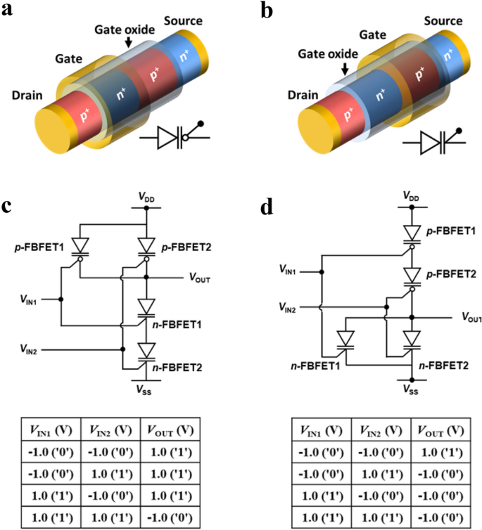
Nand And Nor Logic In Memory Comprising Silicon Nanowire Feedback Field Effect Transistors Scientific Reports
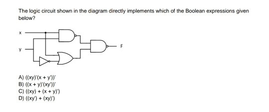
Solved The Logic Circuit Shown In The Diagram Directly Chegg Com
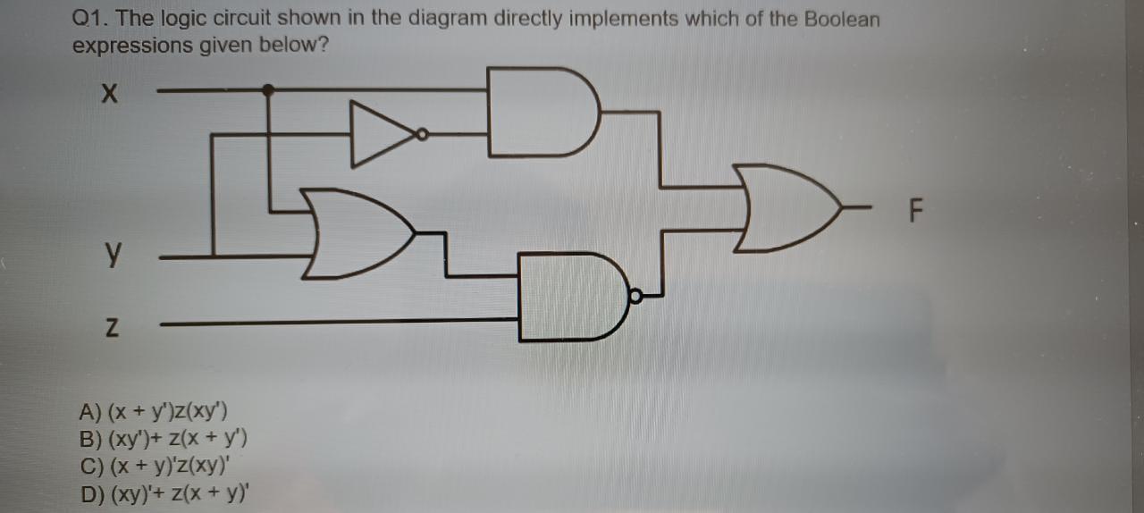
Solved Q1 The Logic Circuit Shown In The Diagram Directly Chegg Com
How To Design A Logic Circuit That Has Three Inputs A B And C And Whose Output Will Be High Only When Majority Of The Inputs Are High Quora
How To Design A Logic Circuit That Has Three Inputs A B And C And Whose Output Will Be High Only When Majority Of The Inputs Are High Quora

Sum Of Product Expression In Boolean Algebra

Identify The Operation Performed By The Circuit Given Below
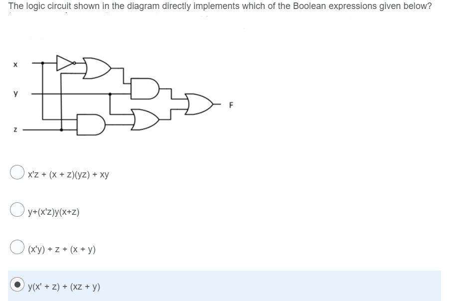
Answered The Logic Circuit Shown In The Diagram Bartleby
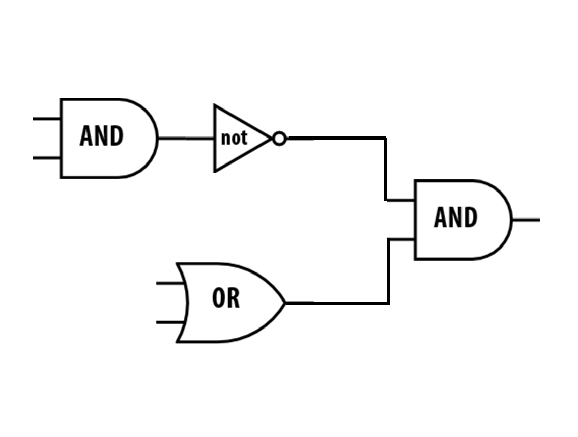
Unit 6 Lab 1 Computer Abstraction Hierarchy Page 9

Solved 9 The Logic Circuit Shown In The Diagram Directly Chegg Com
Logic Circuit Editor

Acm Digital Library Communications Of The Acm

Truth Table An Overview Sciencedirect Topics
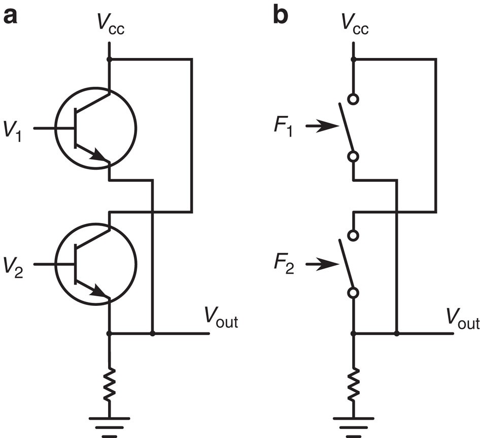
Sub Kbt Micro Electromechanical Irreversible Logic Gate Nature Communications

Implementing Logic Functions Using Only Nand Or Nor Gates Eeweb

The Logic Circuit Shown In The Diagram Directly Implements Which Of The Boolean Expressions Given Be The Logic Circuit Shown In The Diagram Directly Course Hero